Configure BGP for Azure ExpressRoute
Before you begin, ensure you have completed the steps outlined in Add an Azure ExpressRoute Connection to a Cloud Router .
Gather information from the PacketFabric portal
You will be asked to provide the following information:
-
Cloud Router ASN: This is the ASN you set for the PacketFabric Cloud Router. You can find this on the Cloud Router details page or the BGP settings for the connection.
-
Private peering VLAN ID: You can find this in the BGP settings for the connection.
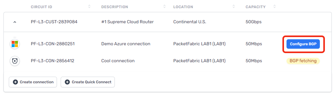
To view the BGP settings, click Configure BGP after the Cloud Router connection finishes provisioning:
-
IPv4 Primary subnet: If you provisioned the connection with a public IP address, this field is supplied. You will need this address if you are configuring Microsoft peering in the Azure portal.
Set up peering
Peering notes and limitations
Each ExpressRoute circuit comes with 4 possible peerings: primary + secondary Private peering, and primary + secondary Microsoft peering (public peering). At this time, we do not support using all 4 peerings from the same ExpressRoute circuit on a single Cloud Router.
On a single Cloud Router, you can have:
-
Primary + secondary Private peering
OR
-
Primary + secondary Microsoft peering
You cannot have a combination of Private and Microsoft peering on the same Cloud Router, if those peerings are on the same ExpressRoute circuit.
If you want to have both Private and Microsoft peering on the same Cloud Router, you will need to create two separate ExpressRoute circuits.
With regards to Microsoft peering:
- Ensure you are provisioning the connection on a Cloud Router with ASN 4556. You can use a private ASN, but that requires additional verification from Microsoft.
- Before you can complete the Microsoft peering in the Azure portal, you need to have two Cloud Router connections (each with a public IP) provisioned. This is necessary to get the primary and secondary IPv4 subnet addresses.
Private peering
From the Azure portal, refresh the ExpressRoute circuit overview page. The provider status should update to the Provisioned status:

Click Azure private to configure a private connection to your Azure VNet.

Select Enable peering and then complete the following fields:
-
Row
- Field
- Description
-
Row
-
Peer ASN
-
Enter the ASN you set for your PacketFabric Cloud Router.
Note that ASNs from 65515 to 65520 are reserved for Microsoft’s internal use.
-
-
Row
- IPv4 Primary subnet
- This is a /30 subnet for your primary link. It can be a public or private IP address range, but it cannot be a range that is already being used in your Azure VNet.
-
Row
- IPv4 Secondary subnet
- This is another /30 subnet. It follows the same rules as the primary subnet, but is used with your secondary link.
-
Row
- VLAN ID
- This is the Private peering VLAN ID found on the PacketFabric BGP Settings page for the connection.
-
Row
- Shared key
- An optional MD5 hash. This must be present on both sides of the tunnel and is limited to 80 characters. Special characters are not supported.
For example:

For more information, see the following Microsoft articles:
Microsoft peering
NOTE:
-
The connections should be on a Cloud Router with ASN 4556 or another public ASN. You can use a private ASN, but that requires additional verification from Microsoft (meaning additional delays).
-
To use Microsoft peering, ensure that you have provisioned your Cloud Router connection with a public IP address.
-
Before you can complete the Microsoft peering in the Azure portal, you need to have two Cloud Router connections (each with a public IP) provisioned. This is necessary to get the primary and secondary IPv4 subnet addresses.
Set up Microsoft peering if you are using Microsoft 365 or Office 365 and would like to provide on-premises users with a dedicated connection. Microsoft 365 apps still require public internet endpoints.

Select Enable peering and then complete the following fields:
- Row
- Field
- Description
- Row
-
ASN
-
Enter the ASN you set for your PacketFabric Cloud Router. Microsoft expects a public ASN here, so ideally you created your Cloud Router with the PacketFabric public ASN 4556.
You can use a private ASN, but Microsoft will need to manually validate it before use. Microsoft will also remove private ASNs from the AS PATH for received prefixes. This means you cannot optimize routing for Microsoft peering.
As mentioned above, you cannot use private AS numbers from 65515 to 65520. These are reserved for Microsoft’s internal use.
-
- Row
- IPv4 Primary subnet
- This is a /30 subnet for your primary link. You can get this from the BGP settings page in the PacketFabric portal (see above).
- Row
-
IPv4 Secondary subnet
-
This is another /30 subnet. Again, you can get this from the BGP settings page in the PacketFabric portal (see above).
Note that this requires that you create a second Cloud Router connection using the same service key, again requesting a public IP address.
-
- Row
- IPv4 Advertised public prefixes
- The prefixes you want to advertise to PacketFabric from your Azure environment. These should correlate to the prefixes you will provide under Allowed Prefixes from Cloud when configuring BGP from the PacketFabric side.
- Row
- VLAN ID
- This is the Private peering VLAN ID found on the PacketFabric BGP Settings page for the connection.
- Row
- Customer ASN
- If you are advertising prefixes that are not registered to the peering ASN, you can use this field to specify the ASN to which they are registered. (Optional)
- Row
- Routing registry name
- The RIR/IRR in which your public IP prefixes and ASN are registered. (Optional)
- Row
- Shared key
- An MD5 hash. This must be present on both sides of the tunnel and is limited to 25 characters. Special characters are not supported. (Optional)
For more information, see the following Microsoft articles:
Add BGP information to the Cloud Router connection
After completing the steps above, return to the Cloud Routers page in the PacketFabric portal.
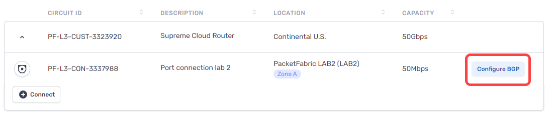
If you have not yet configured a BGP session, you will see the Configure BGP action from the Cloud Routers table:
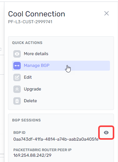
If you have configured the BGP session but wish to make changes, you can access the BGP settings from the BGP Sessions page or by clicking the connection to open its side panel.
From here, click Manage BGP or click the view icon under BGP Sessions:
Complete the following fields:
BGP Settings
- Header row
- Field
- Description
- Row 1
- Azure ASN
- This is the Microsoft ExpressRoute ASN (12076) and cannot be edited.
- Row 1
- Private peering VLAN ID
- This is the VLAN ID assigned to the connection. You must provide this to Microsoft when configuring peering (see above). It cannot be edited.
- Row 1
-
IPv4 primary subnet
-
Enter the same value you provided in the IPv4 Primary subnet field when configuring peering in the Azure portal (see above).
If you created the connection with a public IP, this field is pre-populated.
-
- Row 1
-
IPv4 secondary subnet
-
Enter the same value you provided in the IPv4 Secondary subnet field when configuring peering in the Azure portal (see above). This field only appears if you use the same Azure service key to create a second Cloud Router connection.
If you created the connection with a public IP, this field is pre-populated.
-
- Row 1
- BGP Authentication Key (Optional)
- Enter the Shared key value you provided when configuring peering in the Azure portal (see above).
NOTE ON SUBNETS:
The router peer IP addresses are automatically assigned from this subnet. The first usable IP is allocated to the PacketFabric Cloud Router, and the second is allocated to the Microsoft edge router.
For example, if you enter 192.168.100.128/30, the PacketFabric Cloud Router peer IP address is 192.168.100.129 and the Microsoft peer is 192.168.100.130.
BFD settings
Select Enable BFD to enable Bidirectional Forwarding Detection (BFD) for this connection.
When BFD is enabled, test packets are periodically sent to BGP peers. If a peer fails to reply after a specified interval and number of attempts, the BGP session shuts down.
On its own, BGP will take about 90 seconds to detect a failure and shut down. With BFD, you can detect failures significantly faster.
- Row
- Field
- Description
- Row
- BFD Interval
- The interval (in milliseconds) at which to send test packets to peers. The default is 300 ms, and you can enter a value from 3 to 30000 ms.
- Row
- BFD Multiplier
- The multiplier is the number of consecutive packets that can be lost before BFD considers a peer down and shuts down BGP. The default is 3, and you can enter a value from 2 to 16.
Source NAT settings
- Row
- Field
- Description
- Row
-
Source NAT Direction
-
Egress: Egress SNAT. Traffic leaving the Cloud Router and entering your on-premises/cloud network will be subject to source NAT.
You would typically use this to translate private IP addresses to a public NAT pool as traffic exits your network. For example, 192.168.1.0/24 to 185.161.1.5/32.
Ingress: Ingress SNAT. Traffic leaving your on-premises/cloud network and entering the Cloud Router will be subject to source NAT.
You would typically use this to translate public IP addresses to a private NAT pool when directing traffic elsewhere in your network.
-
- Row
- Prefixes to NAT
- The prefixes from your on-premises environment that you want to associate with the NAT pool.
- Row
-
NAT Pool Prefixes
-
All prefixes that are NATed on this connection will be translated to the pool prefix address.
If this connection uses a PacketFabric-assigned public IP address, then this field should be pre-populated with a newly generated
/32public IP.If this connection uses a private IP address, then enter a
/32prefix that is different than the router peer IPs you entered above and not used on any of your other Cloud Router connections.
-
Destination NAT settings
- Row
- Field
- Description
- Row
- Pre-translation IP prefix
- The destination IP prefix that you want translated via DNAT.
- Row
- Post-translation IP prefix
- The destination IP prefix into which you want DNAT to translate your original (pre-translation) destination IP.
- Row
-
Conditional IP prefix
-
Optional. The prefix being received must fall within the conditional prefix range before the Cloud Router will advertise the pre-translation prefix.
Note that the post-translation prefix must be equal to or included within the conditional IP prefix.
-
Allowed prefixes to cloud
This is a list of addresses that you want to allow into your Azure VNet from other connections within the Cloud Router. You can add up to 1000 prefixes.
If you are using NAT, this is pre-populated with the PacketFabric router peer IP.
The values you set above under Session settings apply to all prefixes. However, you can override those settings on a per-prefix basis.
For example, if you enabled Allow longer prefixes above but want to specify an exact prefix, then you can override the Allow longer setting by selecting Match type > Exact next to that particular prefix.
- Row
- Field
- Description
- Row
- Prefix/Mask
- Enter an allowed IP address range in CIDR format.
- Row
- Match type
- Allow or disallow longer prefixes for this row (see the description above).
- Row
-
AS prepend
-
Number of additional times to add the ASN to the BGP path, resulting in a higher path length. Allowed values are integers from 0 to 5.
Routes with higher path length (a higher ASN prepend value) have a lower priority.
-
- Row
-
MED
-
The multi-exit discriminator (MED) value. Allowed values are integers from 0 to 4294967295.
When the same route is advertised in multiple locations, those with a lower MED are preferred by the peer AS.
-
Allowed prefixes from cloud
This is a list of addresses from within the Azure environment that you want to advertise to other connections on the Cloud Router. This can include the VPC internal space and any routes you have created. You can add up to 1000 prefixes.
The values you set above under Session settings apply to all prefixes. However, you can override those settings on a per-prefix basis.
- Row
- Field
- Description
- Row
- Prefix/Mask
- Enter an allowed IP address range in CIDR format.
- Row
- Match type
- Allow or disallow longer prefixes for this row (see the description above).
- Row
- Local preference
- When the same route is received in multiple locations, those with a higher local preference value are preferred by the PacketFabric Cloud Router. Allowed values are integers from 0 to 4294967295.
Create a virtual network gateway for ExpressRoute
Before you continue, consider whether you want to utilize Azure’s zone-redundant gateways. For more information, see see High Availability and Redundancy in ExpressRoute Connections .
-
Use the search bar at the top of the Azure portal to find and select Virtual network gateways.

-
Click Add.

-
Under Basics, complete the following fields:
- Header row
- Field
- Description
- Row 1
- Subscription
- Select the subscription associated with your virtual network.
- Row 2
- Resource group
- The resource group is autopopulated based on the virtual network you select.
- Row 2
- Name
- Provide a meaningful name for the gateway.
- Row 2
- Region
- Select the region associated with your virtual network.
- Row 2
- Gateway type
- Select ExpressRoute.
- Row 2
-
SKU
-
Select one of the following:
- Standard/ErGw1AZ: 1,000 Megabits/second
- High Performance/ErGw2AZ: 2,000 Megabits/second
- Ultra Performance/ErGw3AZ: 10,000 Megabits/second
The SKUs that begin with
ErGwindicate that the gateway is in a zone-redundant region.If you are planning to implement FastPath, you must select the Ultra Performance gateway.
For more information about the differences between SKUs, see Estimated performances by gateway SKU.
-
- Row 2
- Virtual network
- Select the virtual network to which you are connecting.
- Row 2
-
Public IP address
-
Select a previously created IP address or create a new one. If you are using zone-redundant gateways, the IP address must have a Standard SKU.
For more information, see Microsoft - Public IP addresses.
-
- Header row
-
Click Next to add tags (optional).
-
Click Next and then Create.
Link the virtual network gateway to the ExpressRoute circuit
-
In the Azure portal, go to the overview page for your ExpressRoute circuit.
-
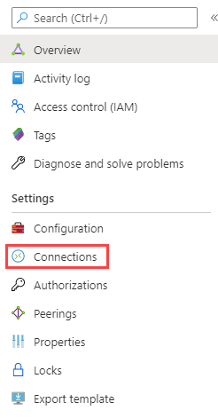
From the menu on the left, select Connections.
-
Click Add.
-
Provide a meaningful name and then click Next.
-
Under Settings, complete the following fields:
- Header row
- Field
- Description
- Row 1
- Virtual network gateway
- Select the gateway leading to the appropriate virtual network.
- Row 2
- Redeem authorization
- Select this if the virtual network is under a different subscription than the ExpressRoute circuit. For more information, see Microsoft - Connect a VNet to a circuit - different subscription.
- Row 2
-
Routing weight
-
The routing weight is relevant when both of the following conditions are met:
-
A virtual network is connected to multiple circuits,
AND
-
Those circuits are advertising the same network prefixes.
In that situation, traffic is sent to the ExpressRoute circuit with the highest routing weight. You can enter a value between 0 and 32000.
-
-
- Header row
-
Click Next to add tags (optional).
-
Click Next and then Create.